A small ode to the CRT
Built October 2018
I used to hate Cathode Ray Tubes. As a kid in Europe, everything flickered at 50Hz, or made a loud whistle at 15.625KHz (back when I could still hear it). CRTs just seemed crude, “electro-brutalist” contraptions from the valve era. They were heavy, and delicate, and distorted, and blurry, and whistled, and gave people electric shocks when they weren’t busy imploding and spreading glass shards around the place.
When I saw the film Brazil, I remember getting anxious about exposed CRTs all over the place — seems I was the kind of kid who was more worried about someone touching the anode or electron gun than the totalitarian bureaucratic world they lived in. 🤷🏻♂️ As ever, I digress.
Now in the 2020s, the CRT is pretty much gone. We have astonishing flat-panel LCD and OLED screens. Nothing flickers, everything’s pin-sharp, multi-megapixel resolutions, nothing whines (except me), and display life is pretty incredible for those of us old enough to remember green-screen computing (but young enough to still see the details).
But, the march to betterness marches away from accessible: if you take apart a phone, the LCD is a magic glass rectangle, and that’s it. Maybe you can see some LEDs if you tear it apart, but it’s really not obvious how it works.
CRTs are also magic, but in a pleasing 19th century top-hat-and-cane science kind of way. Invisible beams trace out images through a foot of empty space. They respond colourfully to magnets (also magic) held to their screens by curious children whose glee rapidly decays into panic, and trying to undo the effect using the other pole before their mother looks around and discovers what they’ve done (allegedly).
The magnet-game is a clue: (most) CRTs use electromagnets that scans the invisible electron beam to light an image at the front. There’s something enjoyable about moving the beam yourself, with a magnet in hand, and you can kind of intuitively figure out how it works from doing this. (Remember the Left-hand Rule?)
I started to warm to CRTs, maybe a fondness when I realised I hadn’t had to seriously use one for over a decade. I wanted to build something. I also like smol displays, and found an excellent source for a small CRT — a video camera viewfinder. Home cameras had tiny CRTs, roughly 1cm picture size, but I looked to find a higher-end professional viewfinder because they tended to have larger tubes for a higher-quality image. Eventually I found a Sony HVF-2000 viewfinder, from ca. 1980.
This viewfinder contained a monochrome 1.5” CRT, and its drive circuitry on stinky 1970s phenolic resin PCBs. All it needs are two turntables and an 8V DC power supply and composite video input. It displays nice, sharp images on a cool white phosphor.
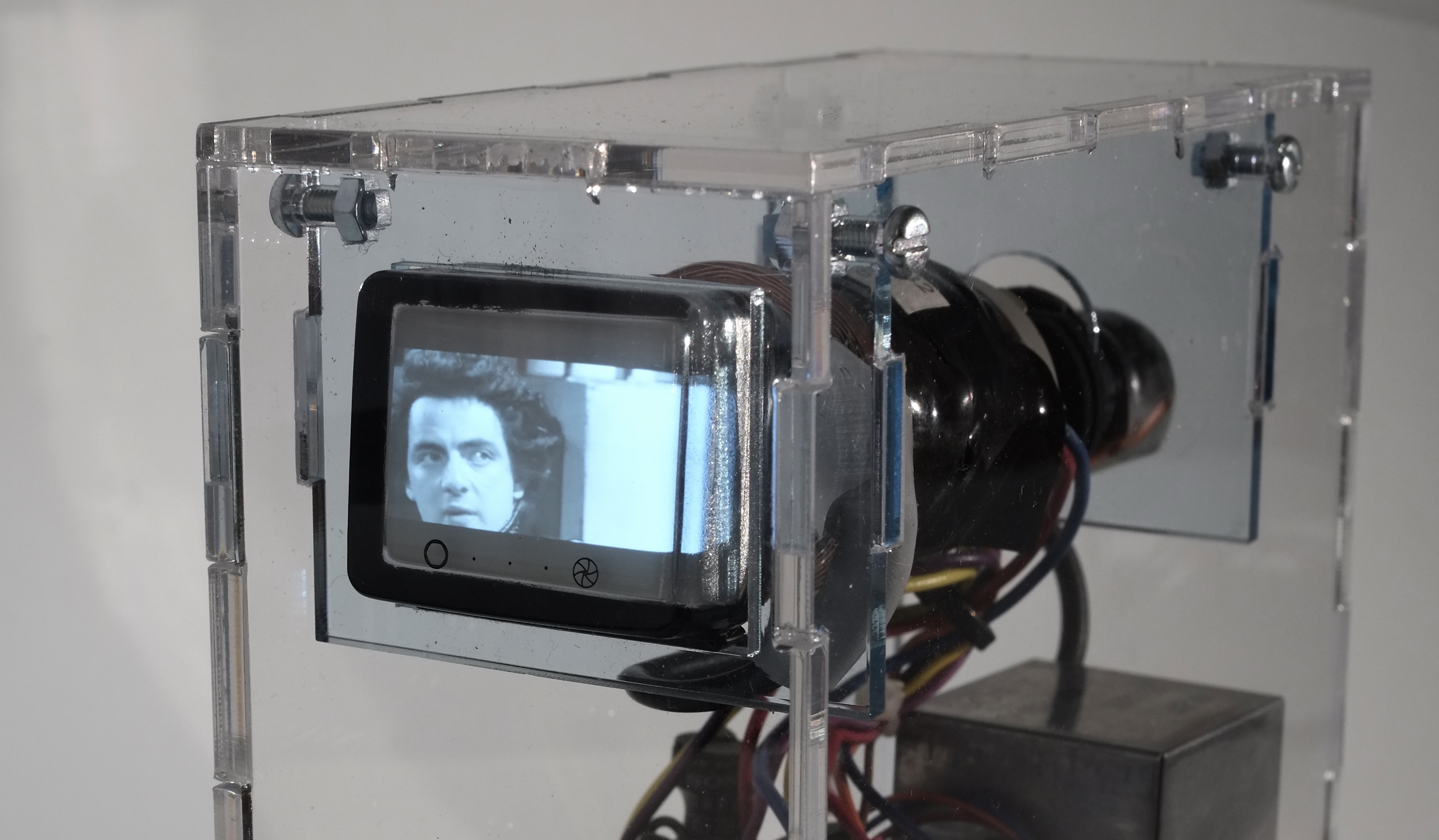
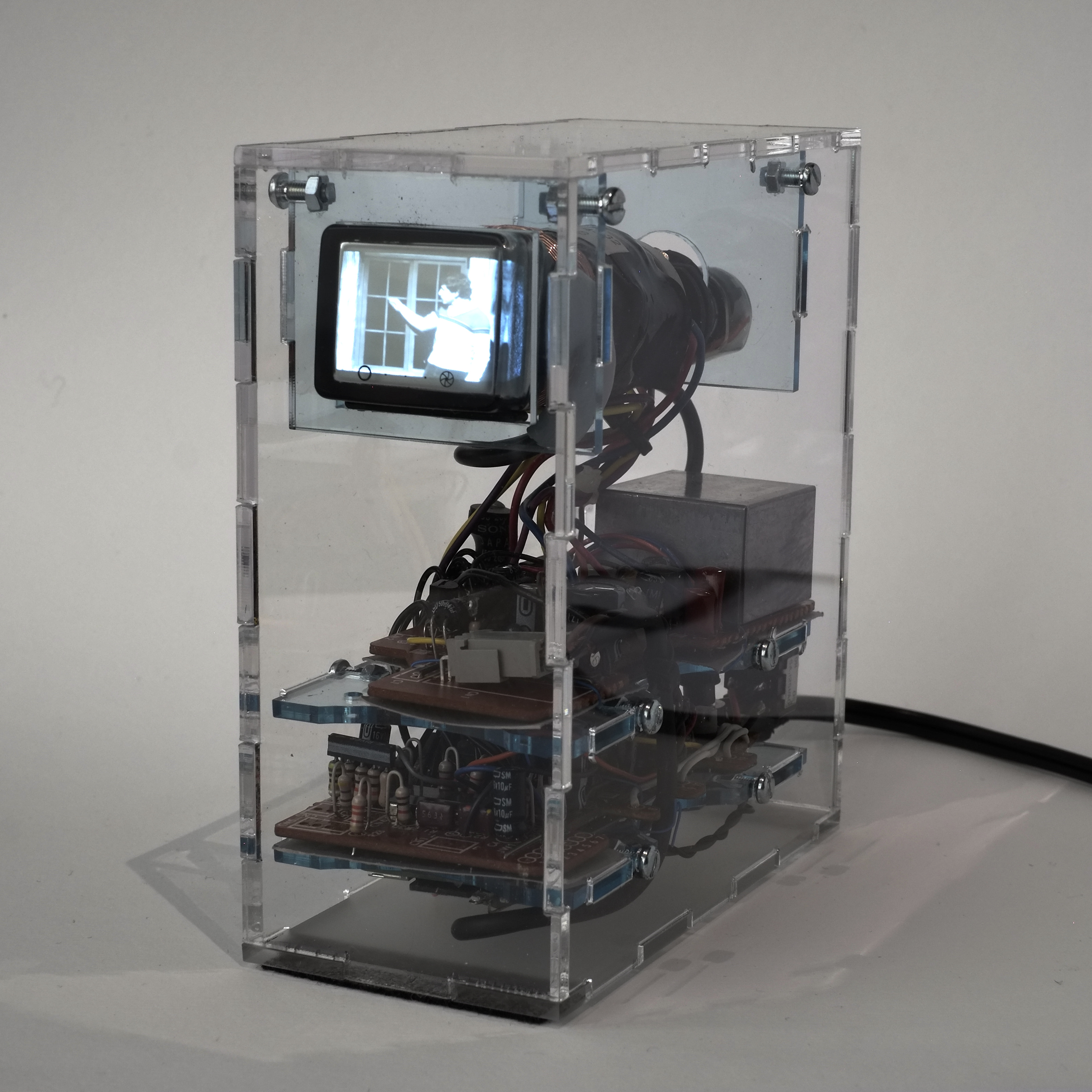
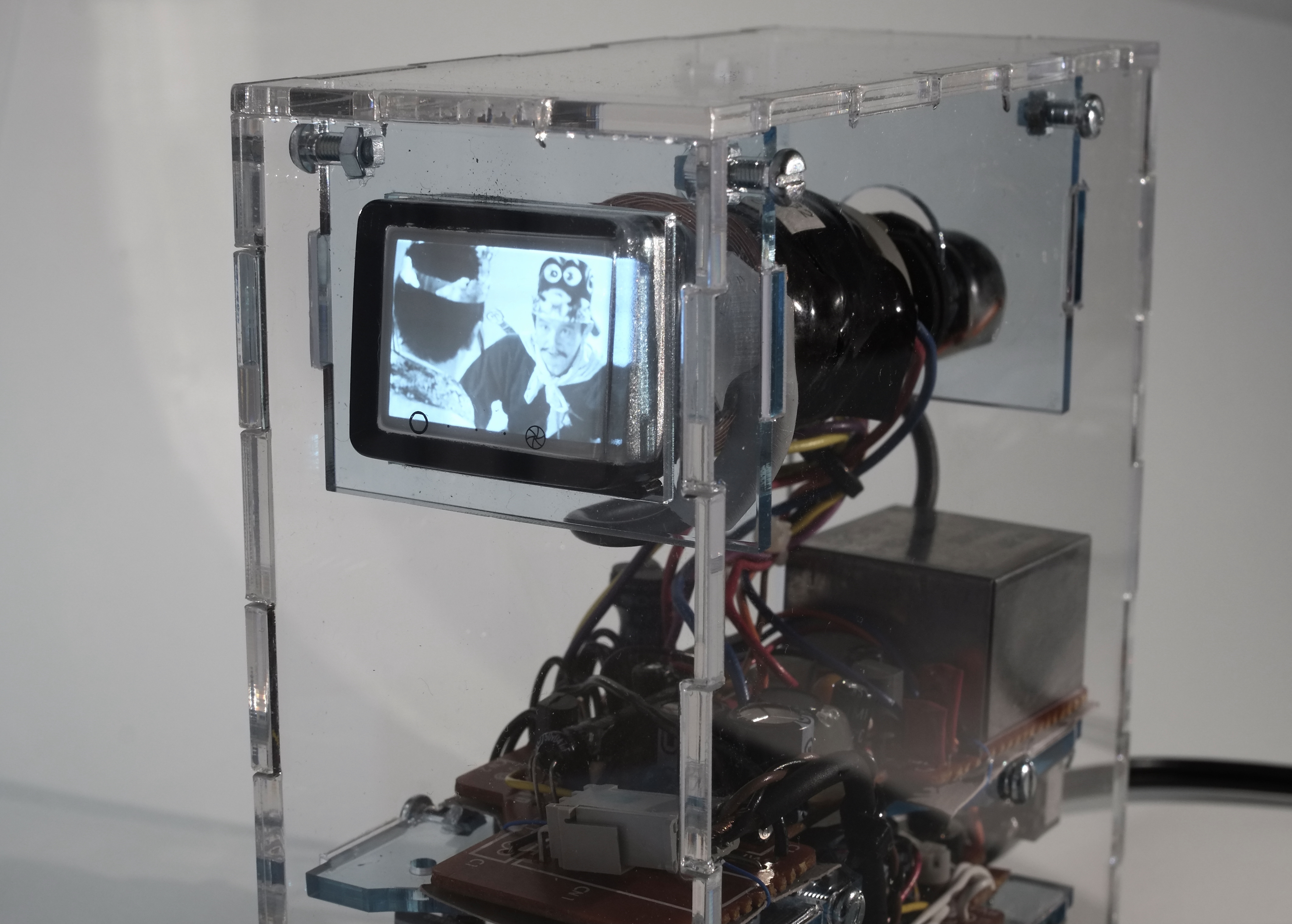
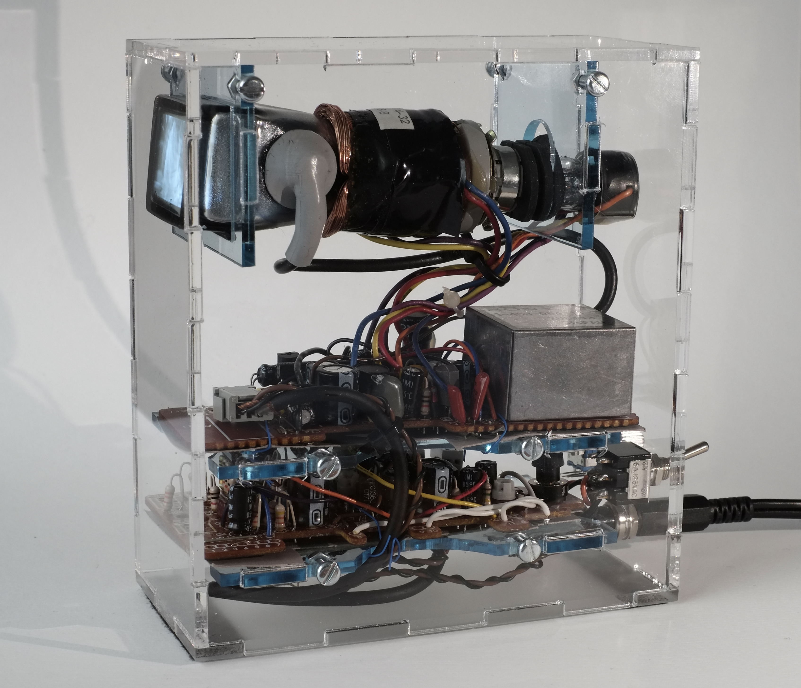
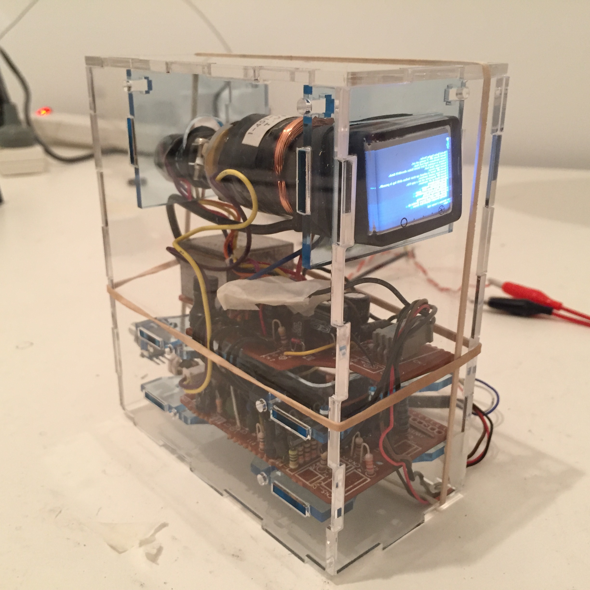
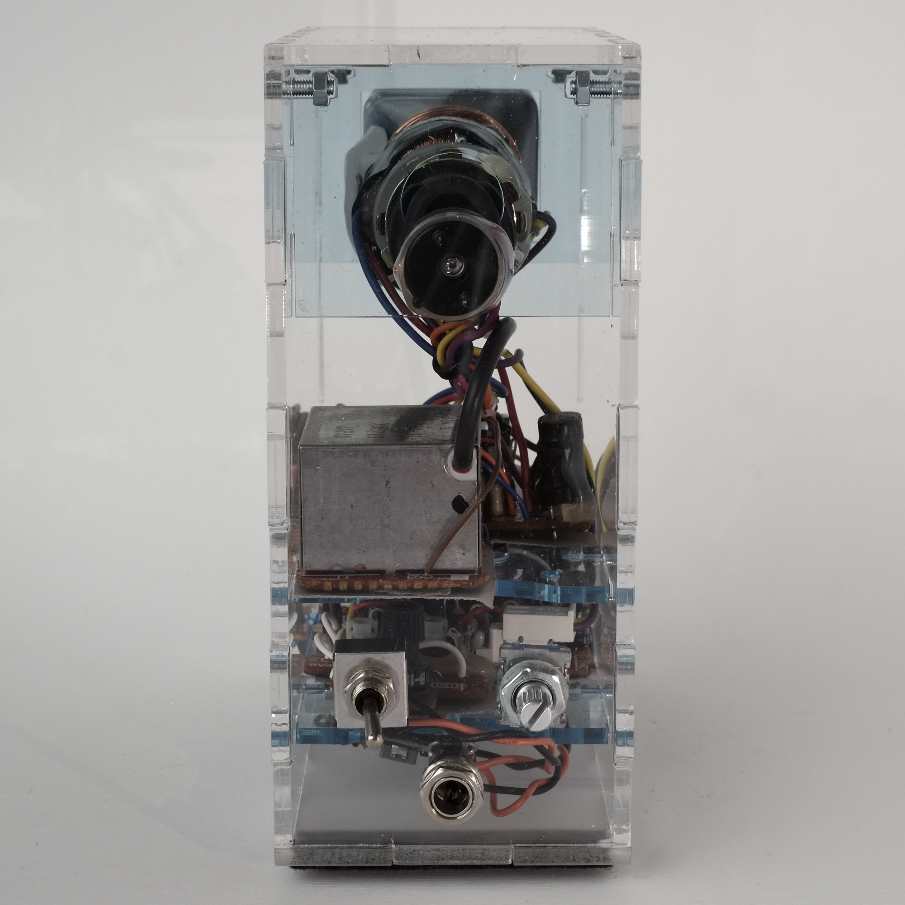
I built this from it:
I wanted to show the CRT from all angles, without hiding any of it, in the trusty “desktop curiosity” style. The idea was to show off this beautiful little obsolete glass thingy, in a way that you could sorta guess how it worked.
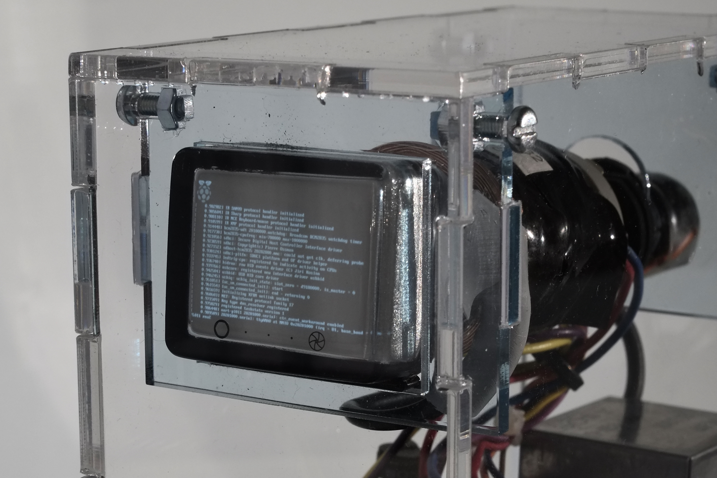
Switching it on with a pleasing clack, it starts silently playing a selection of 1980s TV shows, over and over and over:
I had this on my desk at work, and a Young PersonTM came into my office one day to ask about it. He hadn’t really seen a CRT close-up before, and we had a fun chat about how it worked (including waving a magnet at it – everyone has a spare magnet on their desk for these moments, don’t they? Hello…?). Yay!
If you’re unfamiliar with CRTs, they work roughly like this:
- The glass envelope contains a vacuum.
- The neck contains a heating filament (like a lightbulb) which gives off electrons into the void.
- This “electron gun” is near some metal plates (with variously high positive and negative voltages), which act to focus the fizz of electrons into a narrow beam, directing it forward.
- The inside of the front face of the tube is covered by a phosphorescent material which lights up when hit with electrons.
- The front face is connected to the anode terminal, a high positive voltage. This attracts the beam of electrons, which accelerate to the front.
- The beam hits the front and creates light in a small spot. To create the picture, the beam is steered in rasters/lines using horizontal and vertical electromagnets wrapped around the neck of the tube. (The magnets are called the “yoke”.)
- For PAL at 50Hz, lines are drawn 15625 times a second. Relying on the principle of persistence of vision, this creates the illusion of a steady image.
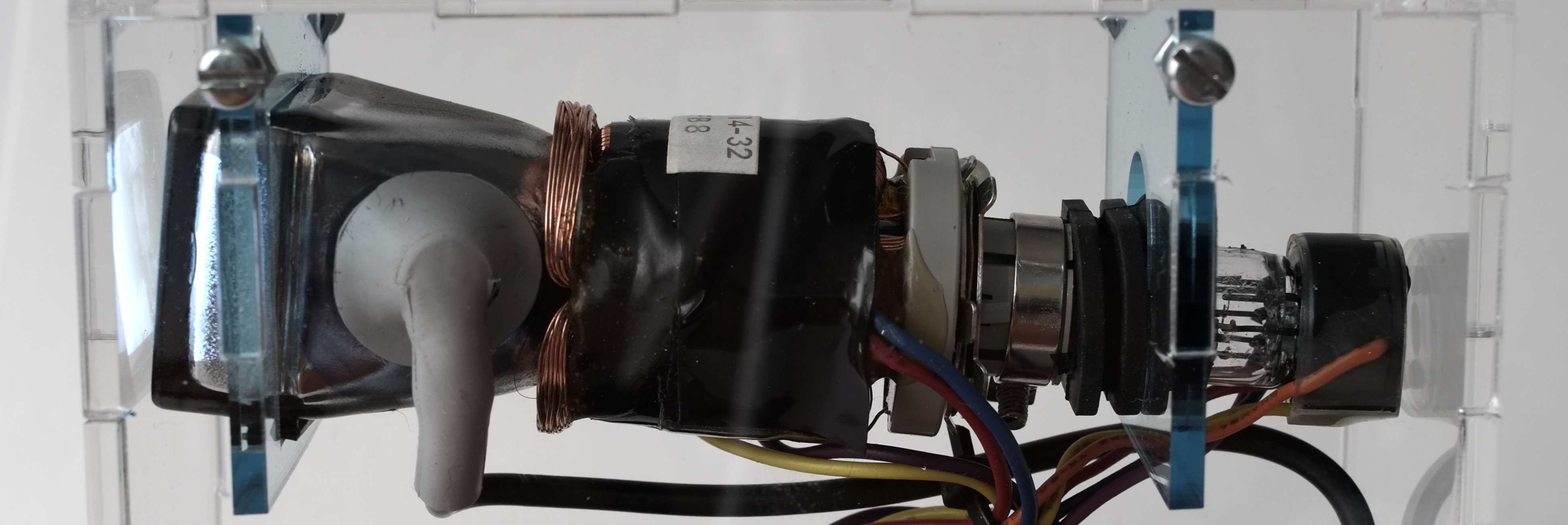
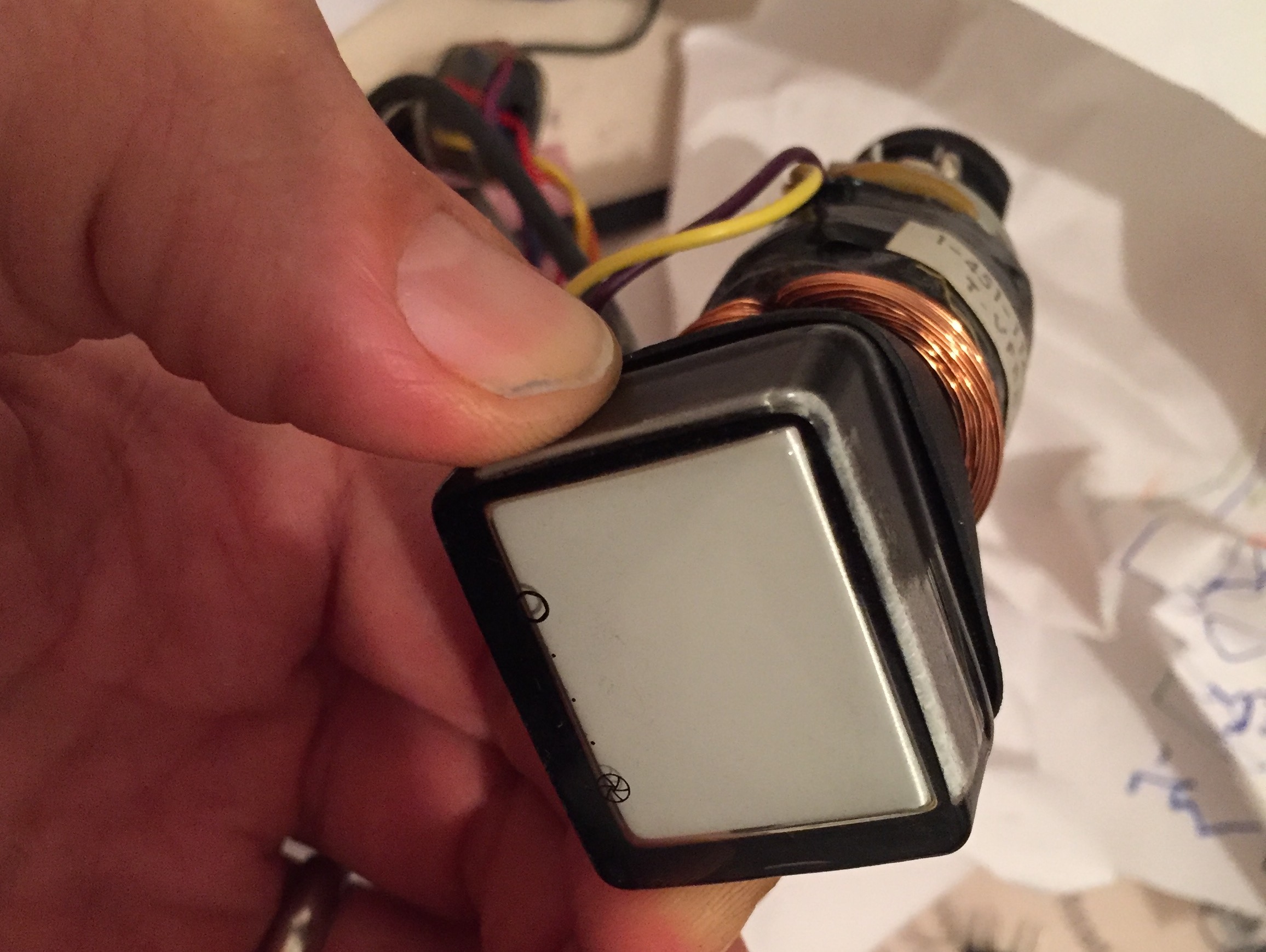
The tube is sealed and electron gun inside is largely invisible, but here you can see the malicious-looking thick anode wire, and how dainty the tube really is with the yoke removed:
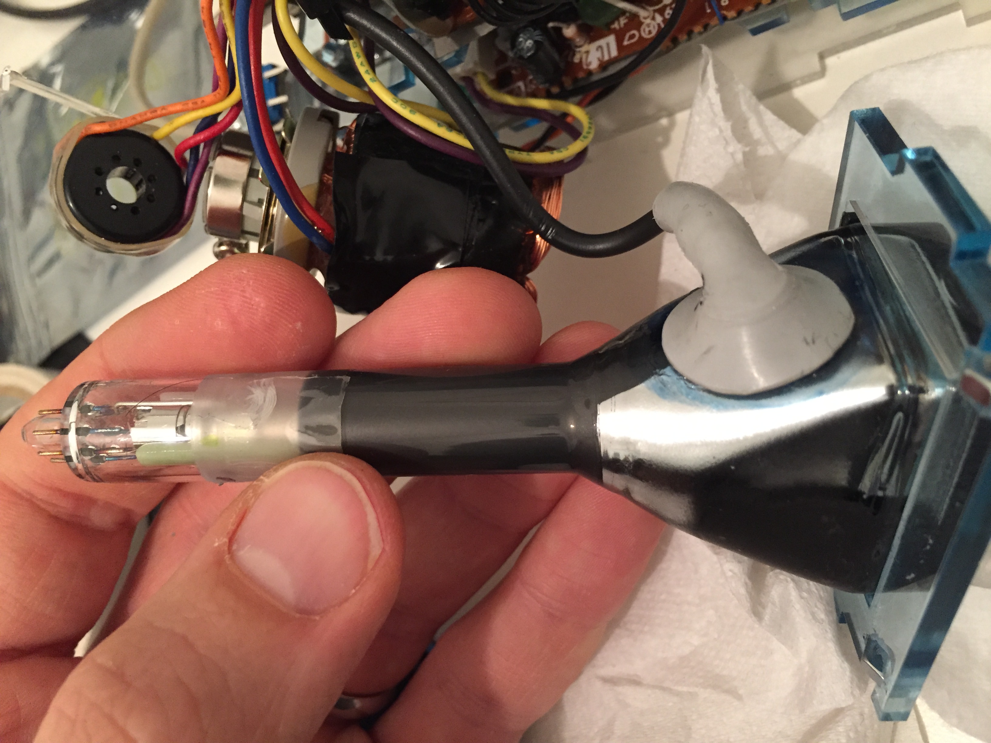
Note: the anode voltage for this tube is, from memory, about 2.5 kilovolts, so not particularly spicy. A large computer monitor will give you 25KV! Did I mention the X-rays?
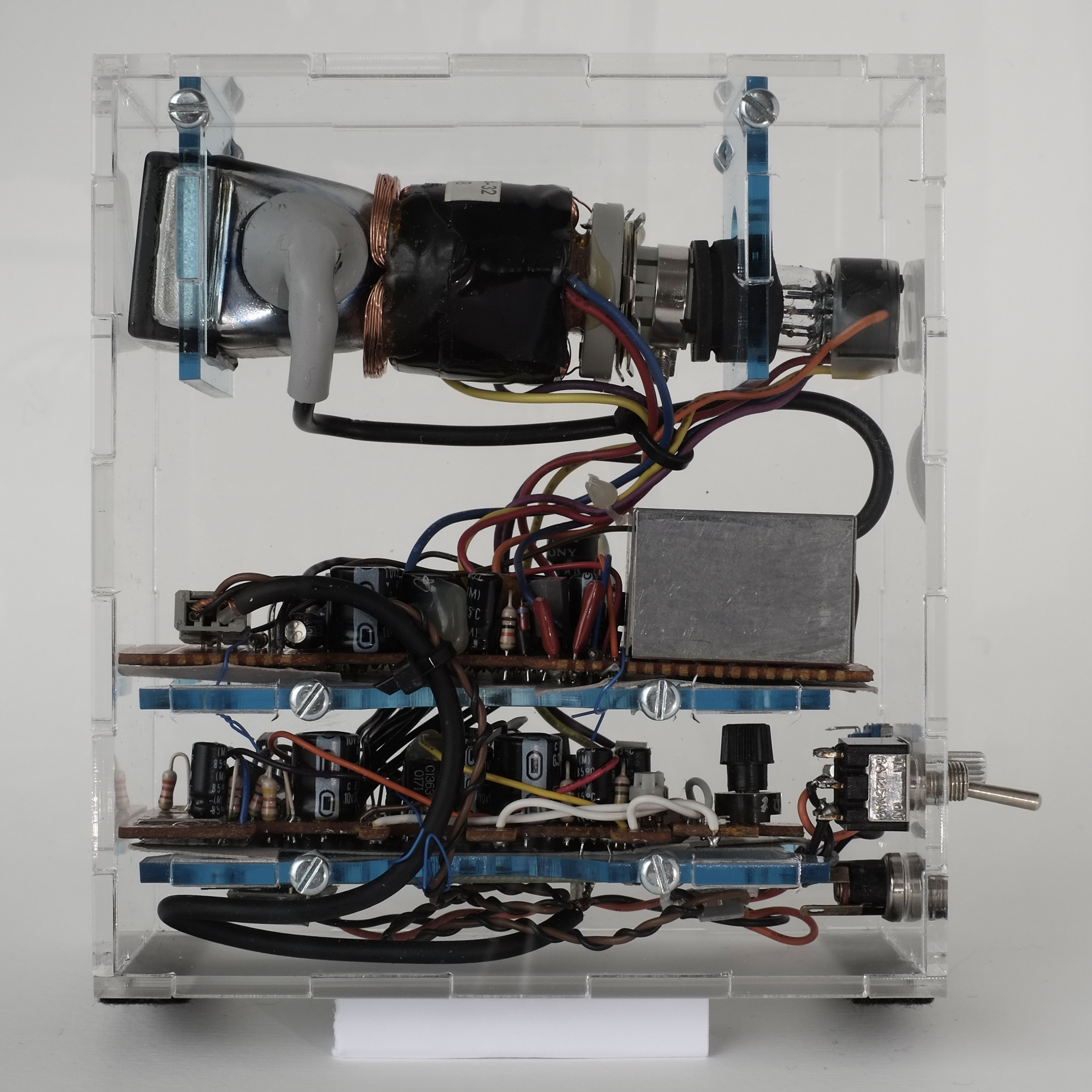
Circuit
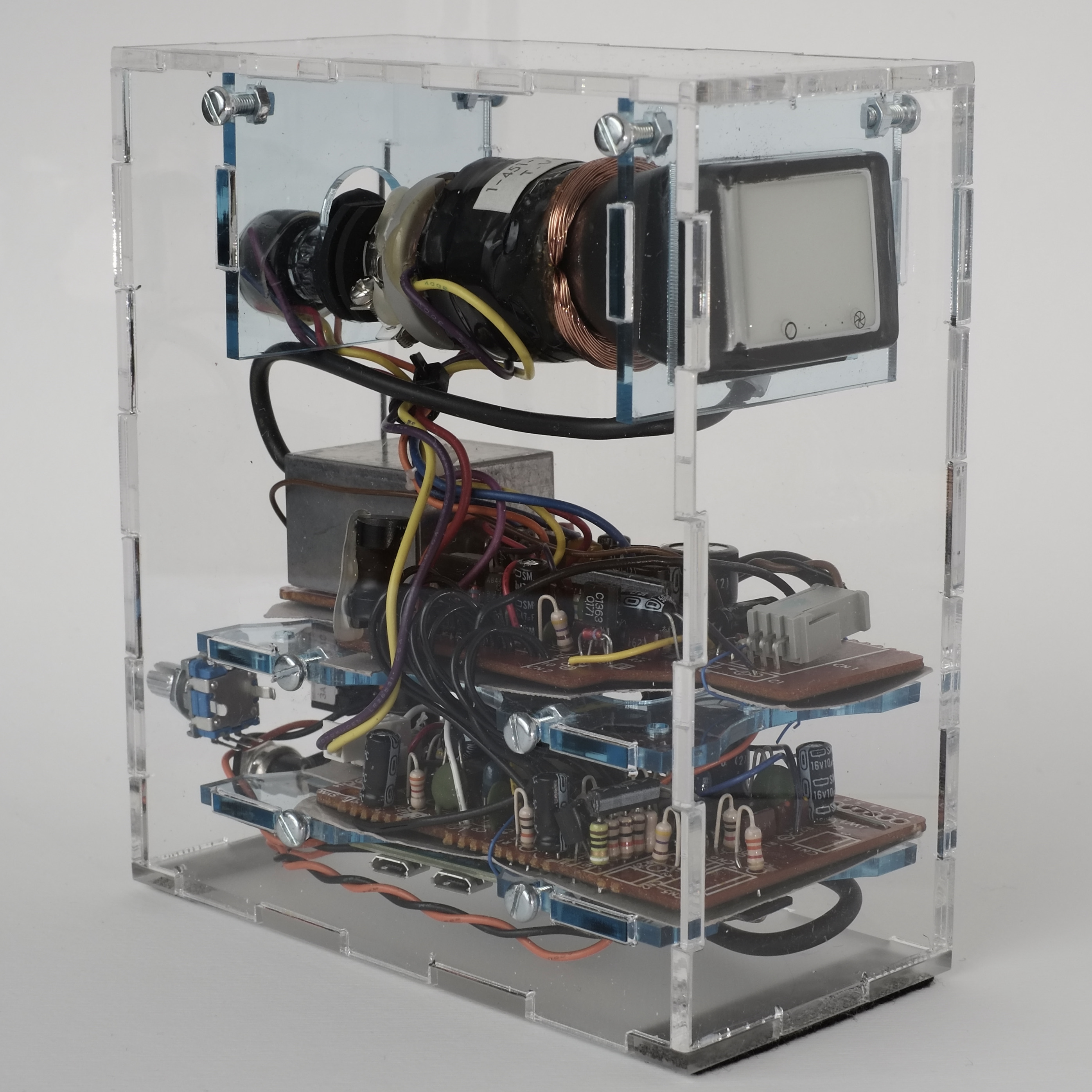
The original viewfinder was a two-board affair, fitting in a strange transverse shape for the viewfinder case. I removed a couple of controls and indicators unrelated to the CRT operation, and extended the wires slightly so they could be stacked.
The viewfinder’s eyepiece looks onto a mirror, turning 90º to the CRT face — so the image is horizontally flipped. This was undone by swapping the horizontal deflection coil wires, reversing the field direction.
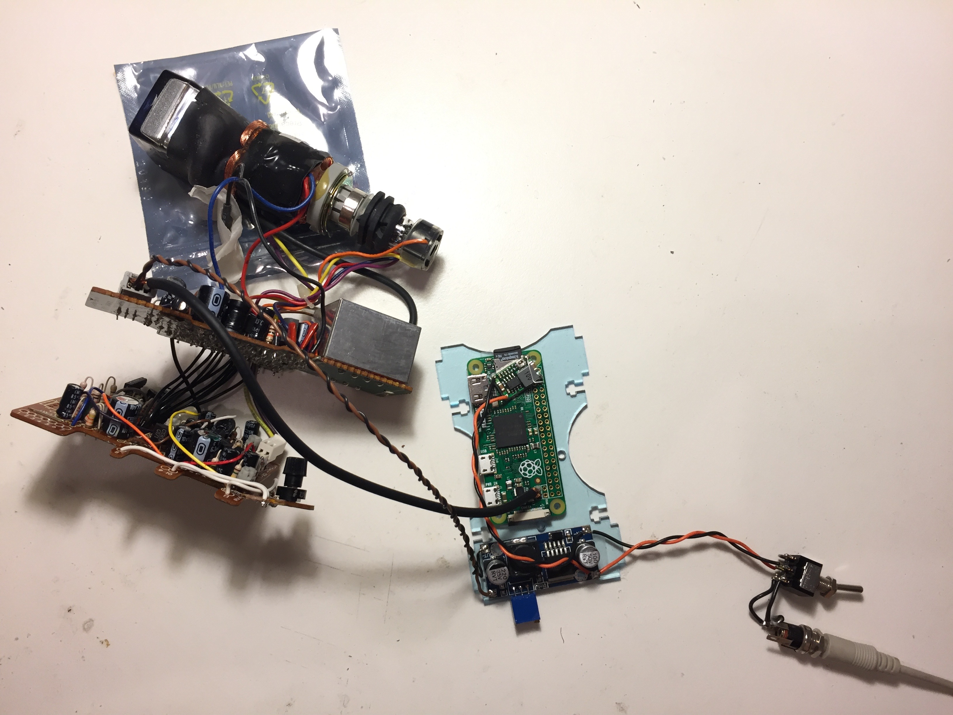
The circuit’s pretty trivial. It just takes a DC input (9-12V) and uses two DC-DC converter modules to create an 8V supply for the CRT board and a 5V supply for a Raspberry Pi Zero layered at the bottom. The whole thing uses under 2W. The Pi’s composite output drops straight into the CRT board. The Pi starts up a simple shell script that picks a file to play. There’s a rotary encoder on the back, to change channel, but I haven’t wired it up yet.
Case
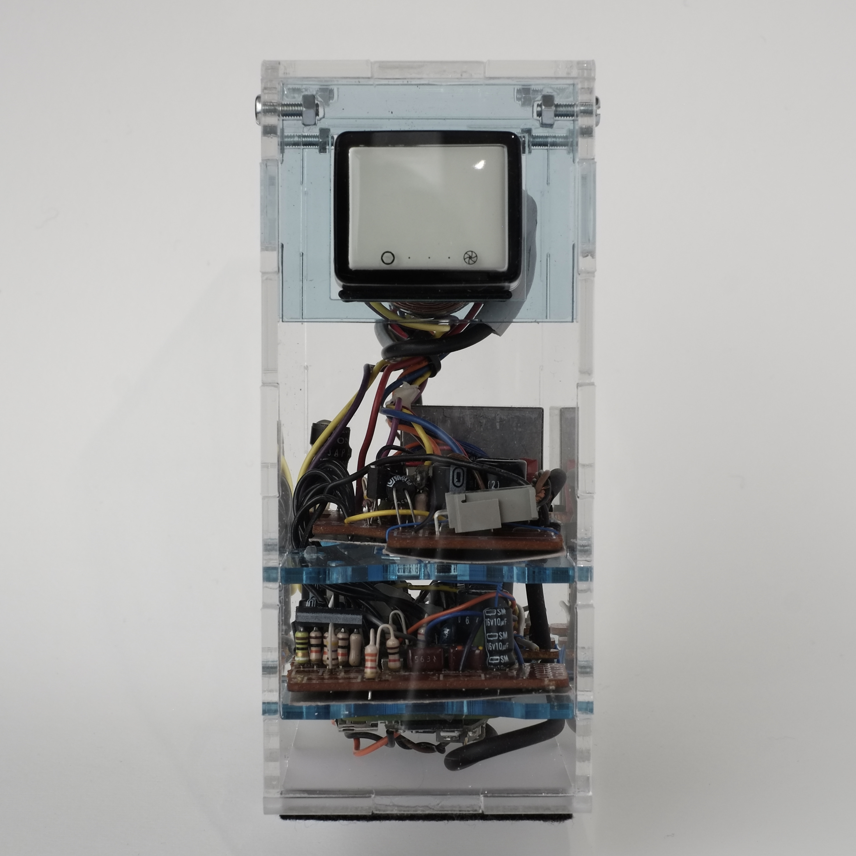
For me, the case was the best bit. I had just got (and since lost :((( ) access to a decent laser cutter, and wanted to make a dovetailed transparent case for the parts. It’s made from 3mm colourless and sky-blue acrylic.
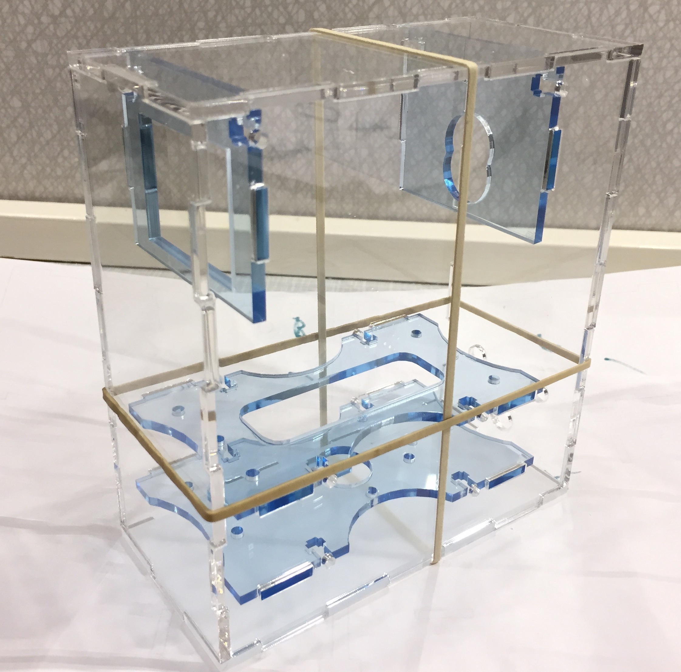
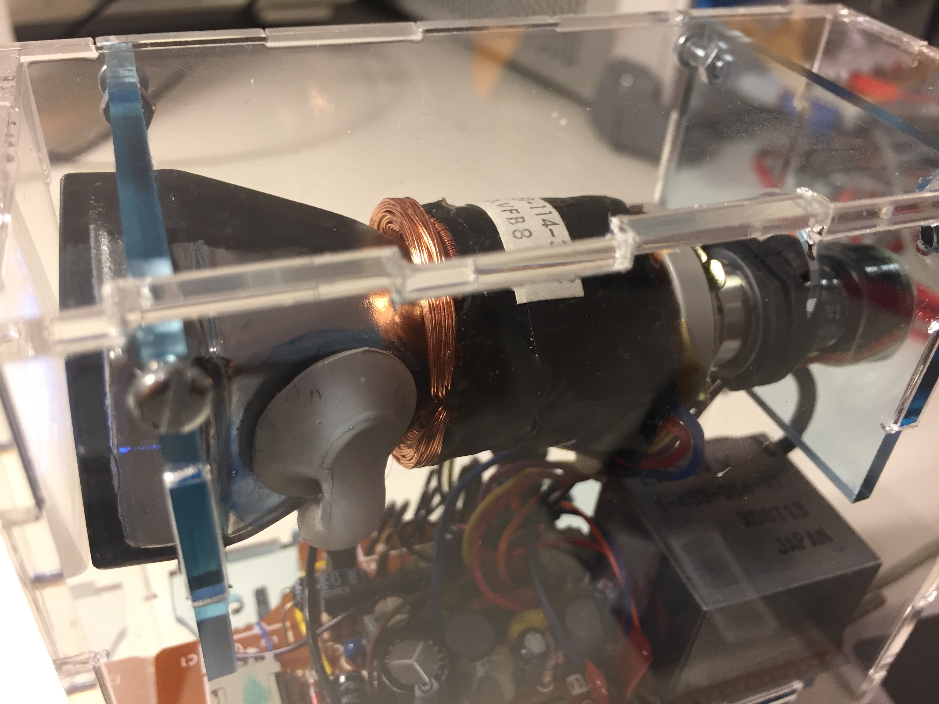
The CRT is supported from two “hangers”, and two trays below hold the circuitry. These are fixed to the sides using a slot/tab approach, with captive nuts. In the close-up pictures you can see there are some hairline stress fractures around the corners of some of the tab cut-outs: they could evidently do with being a few hundred µm wider!
The front/top/back/bottom faces are glued together, then the left/right sides are screwed into the shelves/hangers with captive M3 nuts. This sandwiches it all together.
The back holds a barrel-style DC jack, power switch, and (as-yet unused) rotary encoder. The encoder was intended to eventually be a kind of “channel select”:
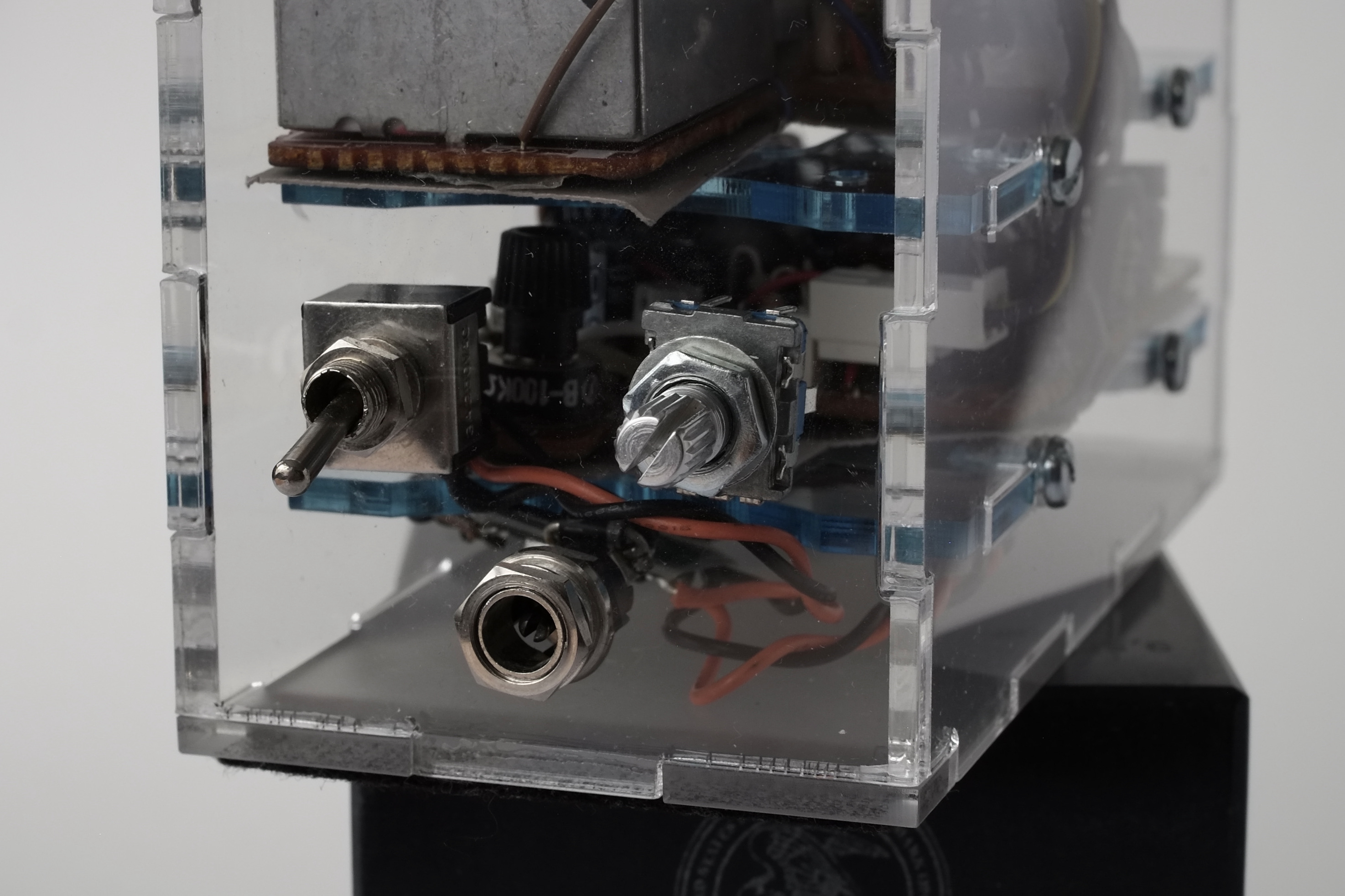
The acrylic is a total magnet for fingerprints and dust, which is excellent if you’re into that kind of thing. There seems to also be little flecks filling the case, probably some aquadag flaking off the CRT. This technology just keeps on giving.
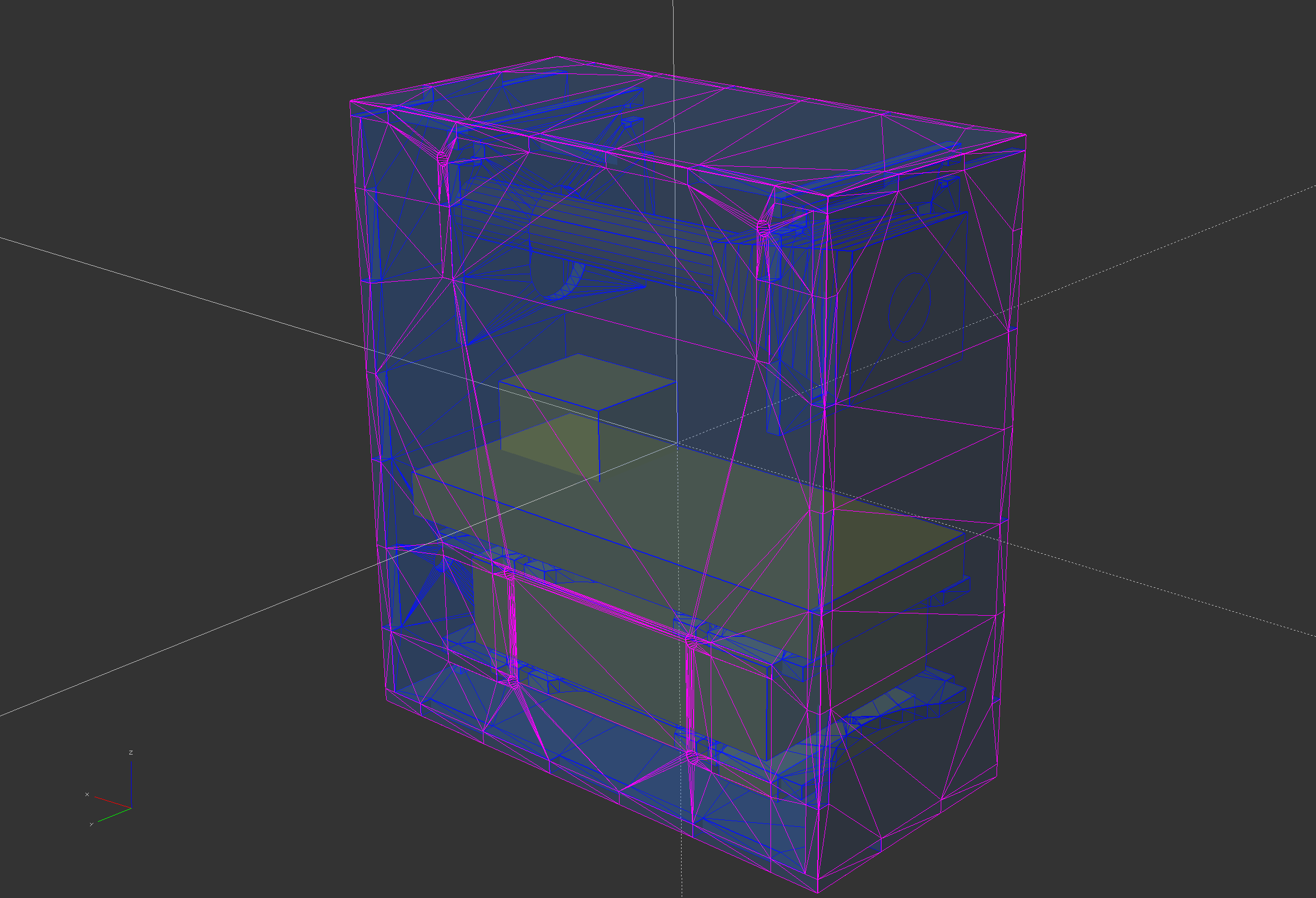
OpenSCAD
The case is designed in OpenSCAD, and is somewhat parameterised: the XYZ dimensions, dovetailing, spacing of shelves and so forth can be tweaked till it looks good.
One nice OpenSCAD laser-cutting trick I saw is that 2D parts can be rendered into a “preview” 3D view, tweaked and fettled, and then re-rendered flat on a 2D plane to create a template for cutting.
So, make a 3D prototype, change the parameters until it looks good (maybe printing stuff out to see whether the physical items actually fit!)…
…then change the mode variable, and the same parts are laid out in 2D for cutting:

Feel free to hack on and re-use this template.
Resources
Pics
-
- Tiny dmesg!
-

- Edmund Esq